Exo Arm Manual
Introduction
This document accompanies the workshop held at IEEE University of New South Wales (UNSW) Sydney student branch during Term 3 2019 where one learns the different skills involved in making an exoskeleton arm (exoarm).
Disclaimer: this project is not the first of its kind. In fact, this project took inspiration from Eduexo and Exbow . Nevertheless, as the motto of UNSW “Manu et Mente” says, we hope to encourage learning by hand and mind.
Why Wearable Robotics?
Wearable robotics can enable or enhance movement which can be used in performance enhancement, rehabilitation, and tele-operation applications.
State of the art
For exoskeletons used in spinal cord injury (SCI) applications, several reports have demonstrated that these exoskeleton systems are safe . Exoskeletons require each patient to do some sort of calibration for 2 - 3 sessions of 10 - 30 minutes fitting plus at least 1 hour of safety procedures. The typical walking speed is 0.2 m/s (max of 0.7 m/s for some devices). In contrast, average walking speed is 1.4 m/s.
Some limitations are as follows:
Designed for <100 kg patients making obese patients out of scope.
Low metabolic cost during exoskeleton training can be bad for the patients health.
Further limited by patient’s limited range of motion, weak bone health, and prone to pressure injuries.
Requires a well-trained caregiver
Very prohibitive cost
Hardware Overview
Fig. [fig:s00-exoarm-snapshot] (below) shows a snapshot of the exoskeleton arm.
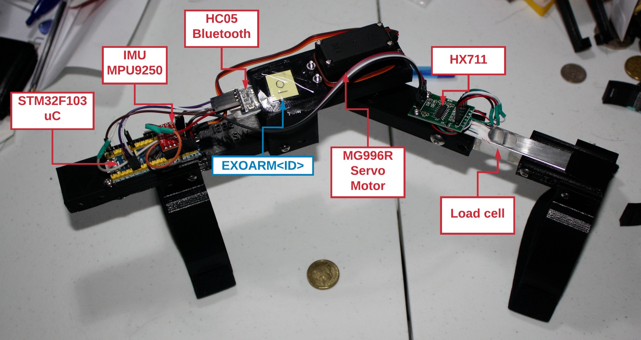
Table [tab:exoarm-pin] (below) shows the pin connections from the sensors to the microcontroller.
| Description | |
|---|---|
| On Board LED | PC13 |
| Load Cell (Force Sensor) | $D_{out}: PC14 SCK: PC13 |
| Motor | PB1 |
| Bluetooth | PA9, PA10 |
| IMU I2C | SDA: PB7, SCL: PB6 Power: PB8, GND: PB9 |
Table [tab:s00-exoarm-bom] (below) shows an overview of the bill of materials. If time and resource permits you, we encourage you to buy the corresponding parts and make your very own exoskeleton arm following this manual.
| Item | ||
|---|---|---|
| USB to Serial PL2303 | 1 | $ 4.00 |
| STM32F103 uC (AKA blue pill) | 1 | $ 4.00 |
| HC-05 Bluetooth | 1 | $ 7.00 |
| 1 | $ 20.00 | |
| MG996R Servo Motor | 1 | $ 7.00 |
| Load cell 5Kg + Hx711 | 1 | $ 8.00 |
| Total | $ 50.00 |
[tab:s00-exoarm-bom]
Why STM32 Microcontroller?
STMicroelectronics is one of the largest suppliers of microcontroller units (MCU) and their products are found in most embedded systems today. It would be beneficial for students to be exposed in MCUs used in the industry such as STM32 as opposed to using Arduino boards which are not meant to be used on commercial products but mainly used to quickly implement or demonstrate simple projects. Moreover, the STM32F0 has superior hardware specifications compared to ATMEGA328 on Arduino boards.
STM has developed and continuously supporting its own HAL (Hardware Abstraction Library) which not only helps developers in quickly and easily setting up the microcontroller, but also provides basic libraries for the MCU’s different systems such as communications (UART, SPI, I2C), memory management, USB, etc. STM HAL supports all families and every series of the STM MCUs, so it would be easy for developers to just use the library on other MCU which might be more suitable for the application. Arduino also has its own libraries, but are done in high level in which most hardware-software integration are obfuscated to the users.
See quora and udemy for further discussions on why STM32. In this workshop, we will be using an MCUs used in the industry with the Arduino library (i.e., STM32duino instead of STM HAL) as students are more likely to be familiar with the Arduino environment.
S01 - 3D CAD Design
In this section, we will be teaching the basics of CAD model design with the intention of 3D printing the parts that will be created. As a tutorial, we will shown how to design the cuff part of the exoskeleton arm and leave the reader to designing the full exoskeleton arm.
Work environment setup
Register to onShape link as shown in Fig. [fig:s01-onshape-registration] using your school (UNSW) email address and avail your free Education subscription. Similar CAD tools may also be used.

Making the cuffs
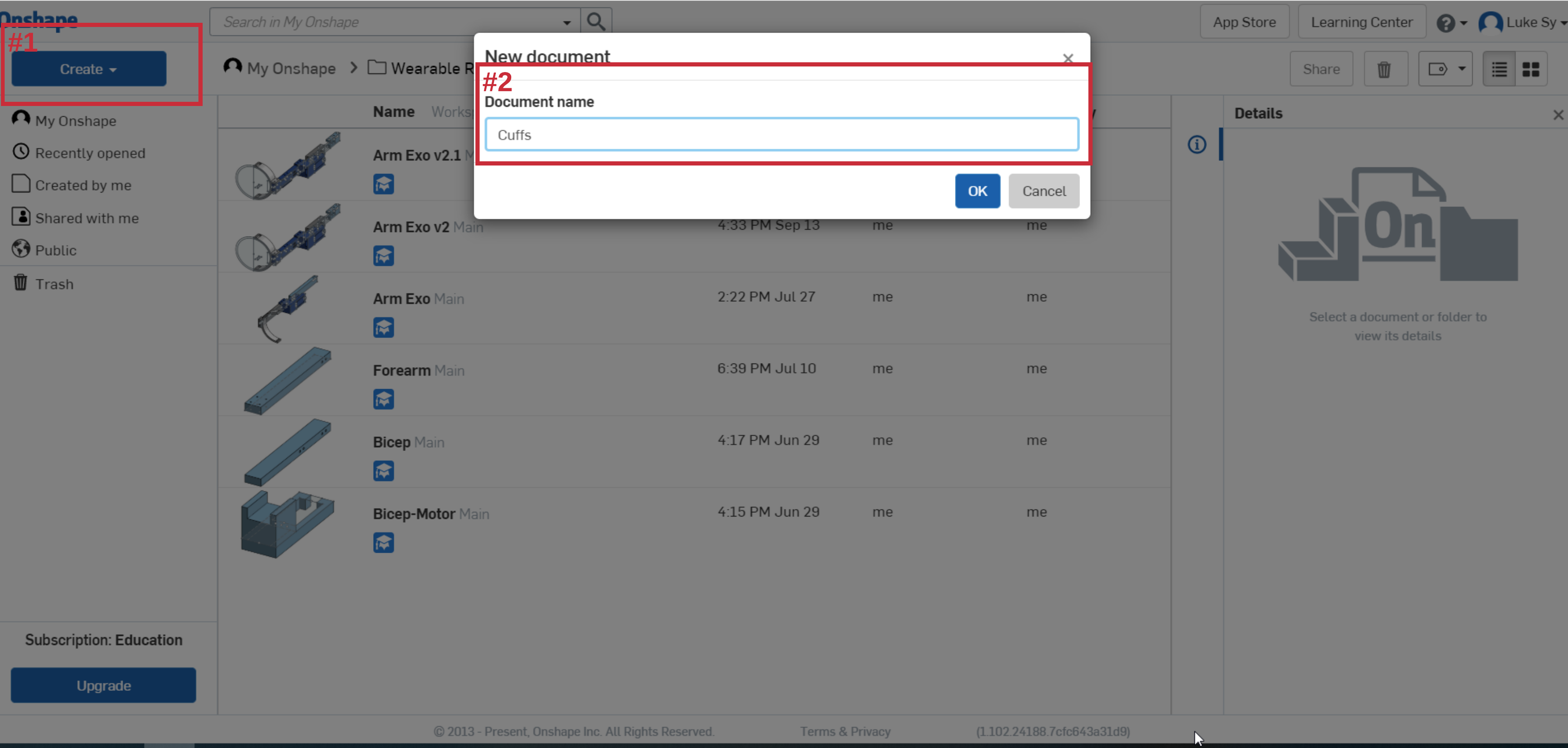
Create a document (#1) and set document name (#2) as shown below.
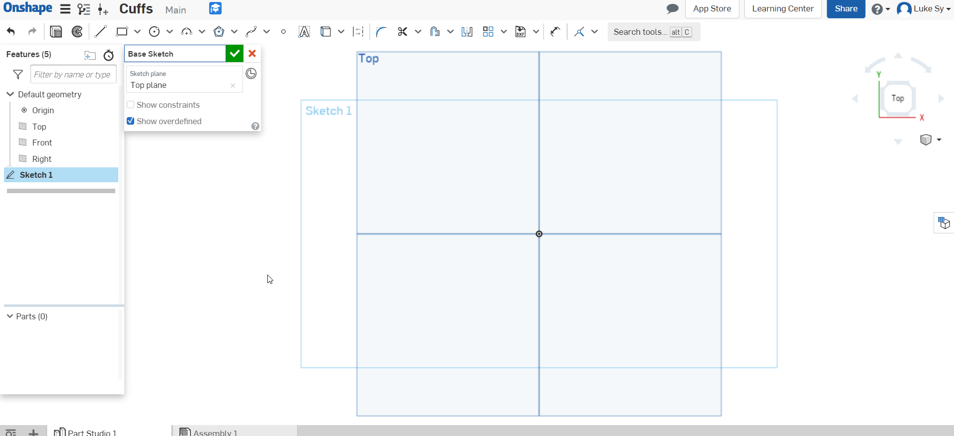
Create a new sketch and select the Top plane as shown below.
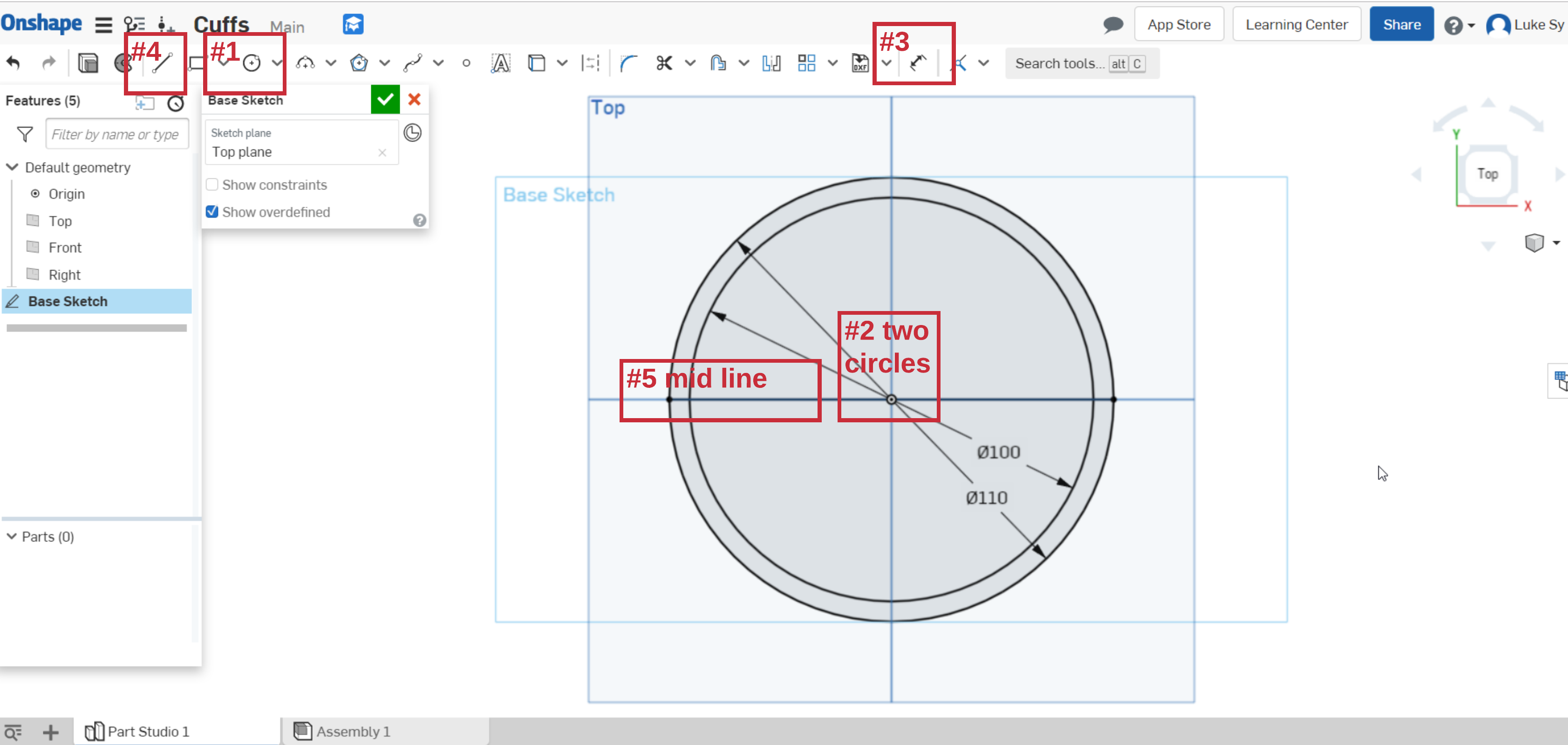
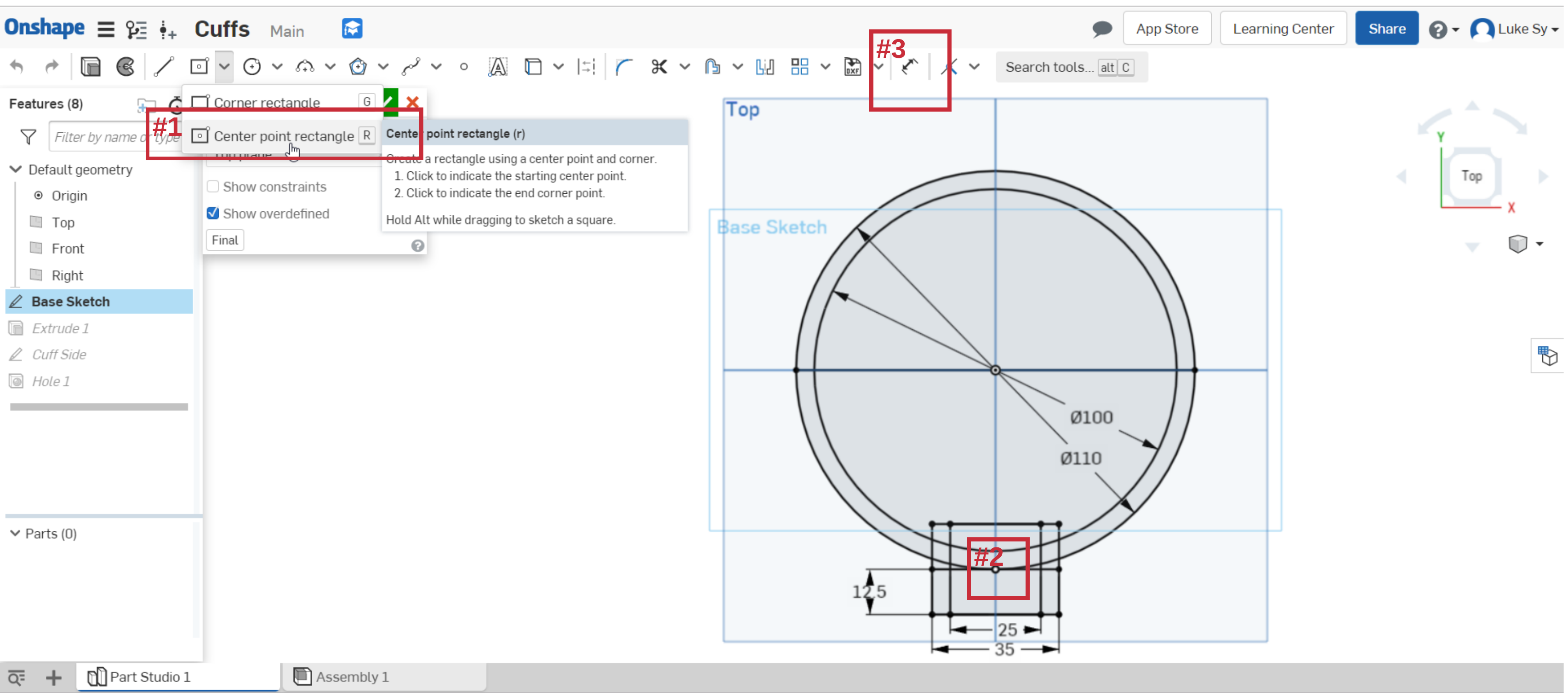
Draw two concentric circles let’s say 100 mm and 110 mm. You can reduce these diameters depending on your wrist or arm diameter. To draw a circle click the circle icon (#1). For simplicity, set the center to the center of the top plane (#2) with any arbitrary size. The size can be adjusted using (#3). Click it and lay it on the circle created. Double click on the length and change to what you require. Lastly, add a mid-line using (#4). Clicking the line segment icon (#4) and lay it on the middle of the circle (#5).
Next, we will make the rectangle that will connect the cuff to the exoskeleton arm. Draw a Center point rectangle by clicking (#1). Lay two rectangles on the lower intersect of the vertical line and the outer circle as shown in (#2). Set the width and length as shown in the figure below using (#3).
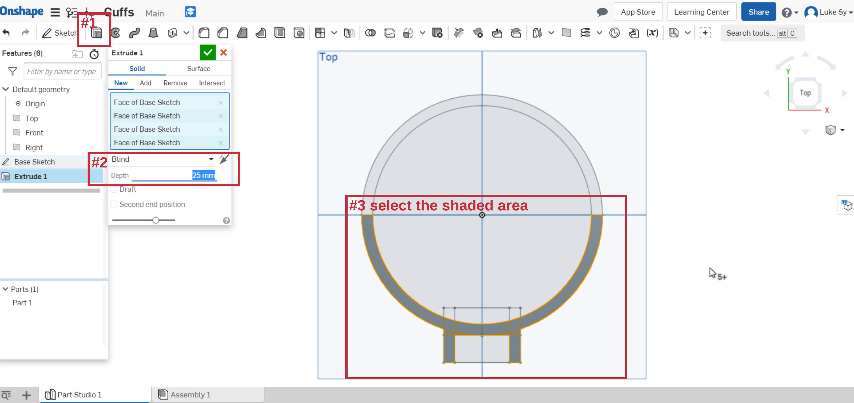
Extrude the relevant sections of the cuff sketch as shown in the figure below by clicking on the Extrude tool (#1). Set the depth to 25mm (#2) and select the appropriate sections (#3).
If viewing the model at 3D view, it should look something like the figure below.
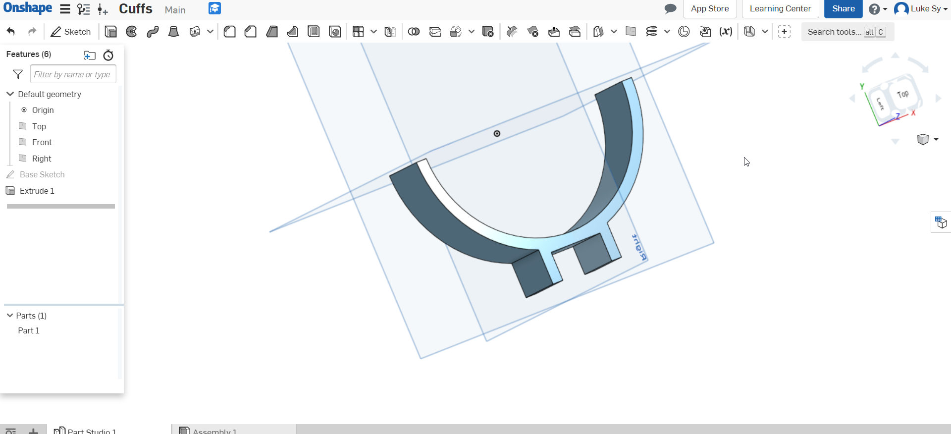
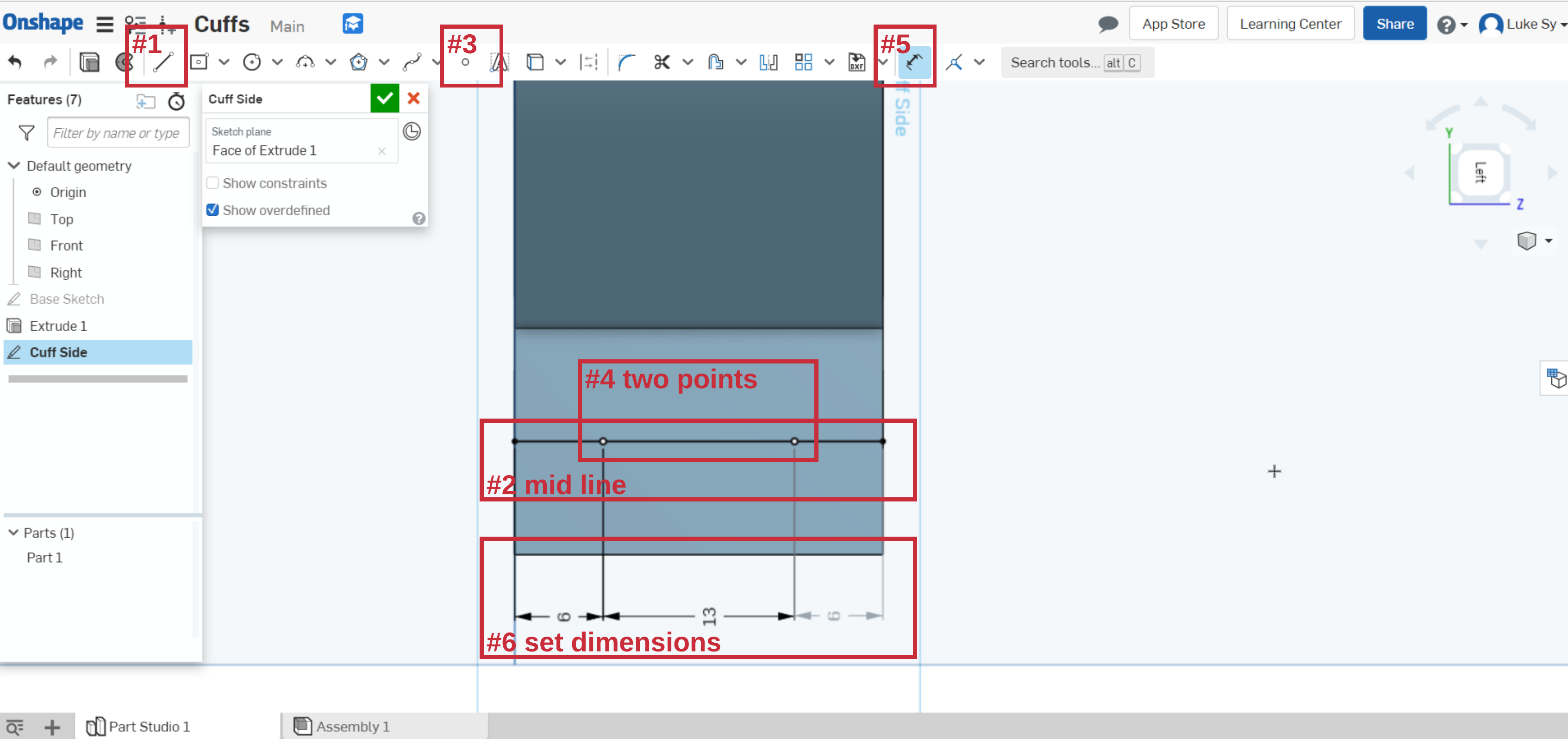
Next, holes will be added on the cuffs. One for the screw that will attach it to the exoskeleton arm, the other for the straps that will fasten the cuff to your arms. To begin, make a sketch on the side of the cuff.
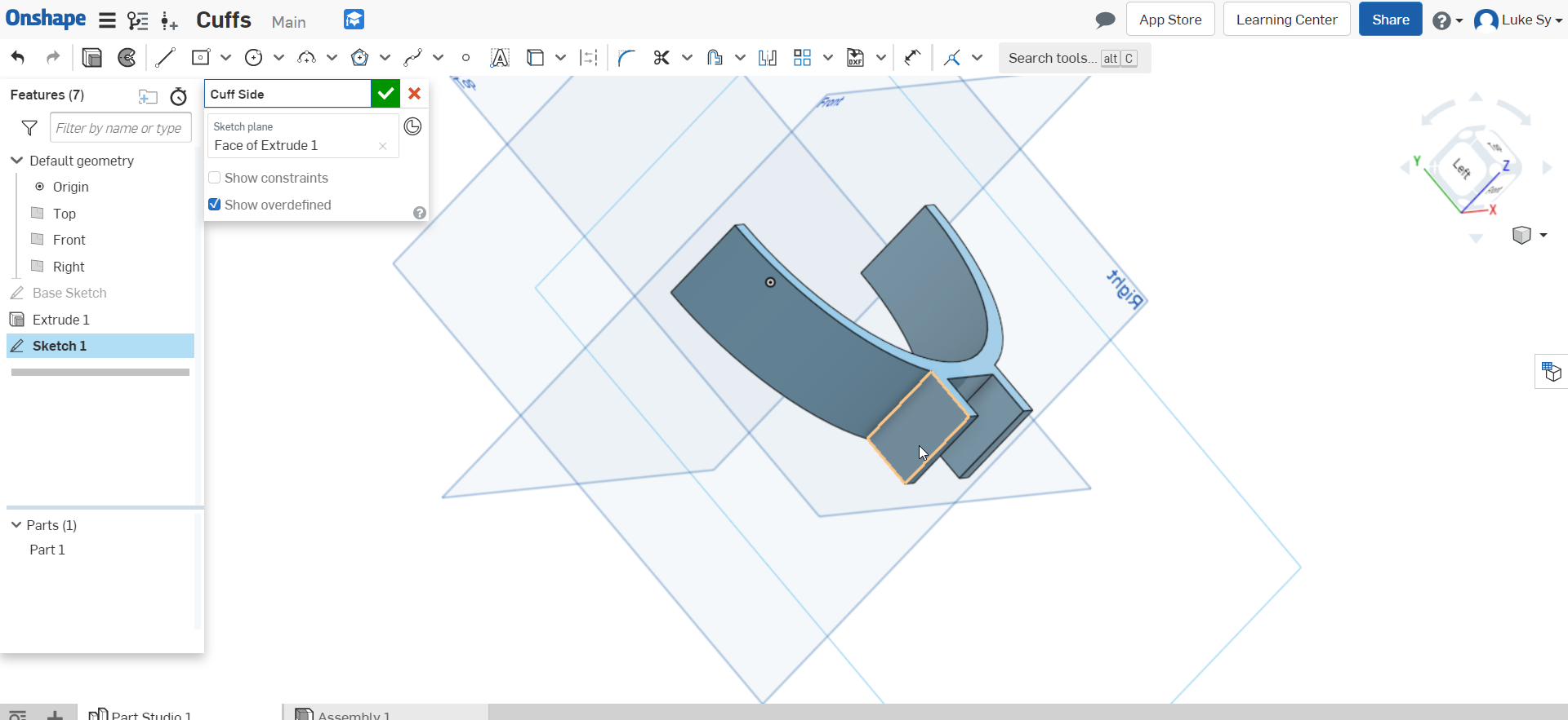
Add two points with the dimensions as shown in the figure below. The holes will be created from these points. First, add a line segment in the middle of the rectangle using (#1) as can seen from the side view (#2). Add two points along the line at arbitrary positions (#3 and #4). Set the distances between the points as specified in the figure (#5 and #6).
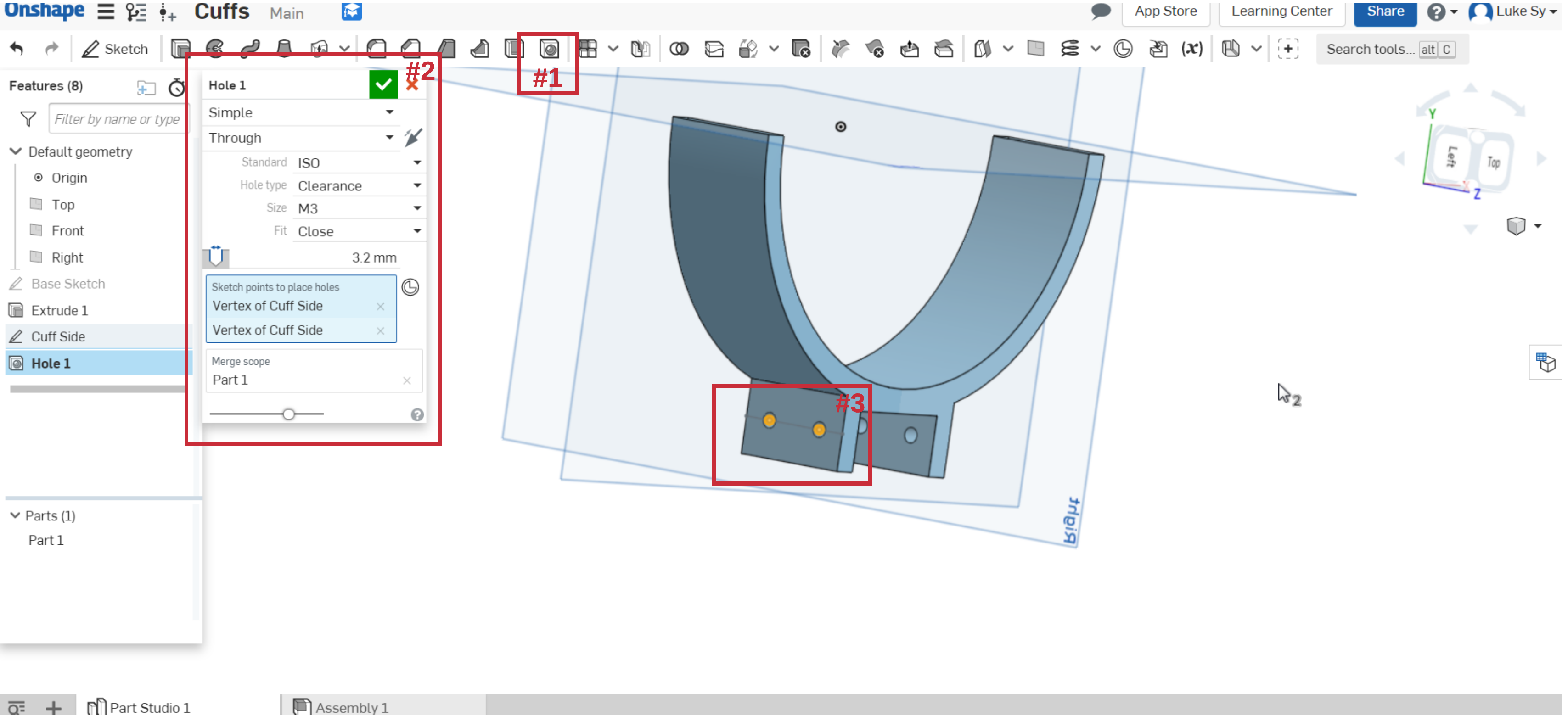
Add holes from the two points made in the prior step. Click the hole icon (#1), set the appropriate settings as shown in (#2), and select the corresponding points for the hole (#3).
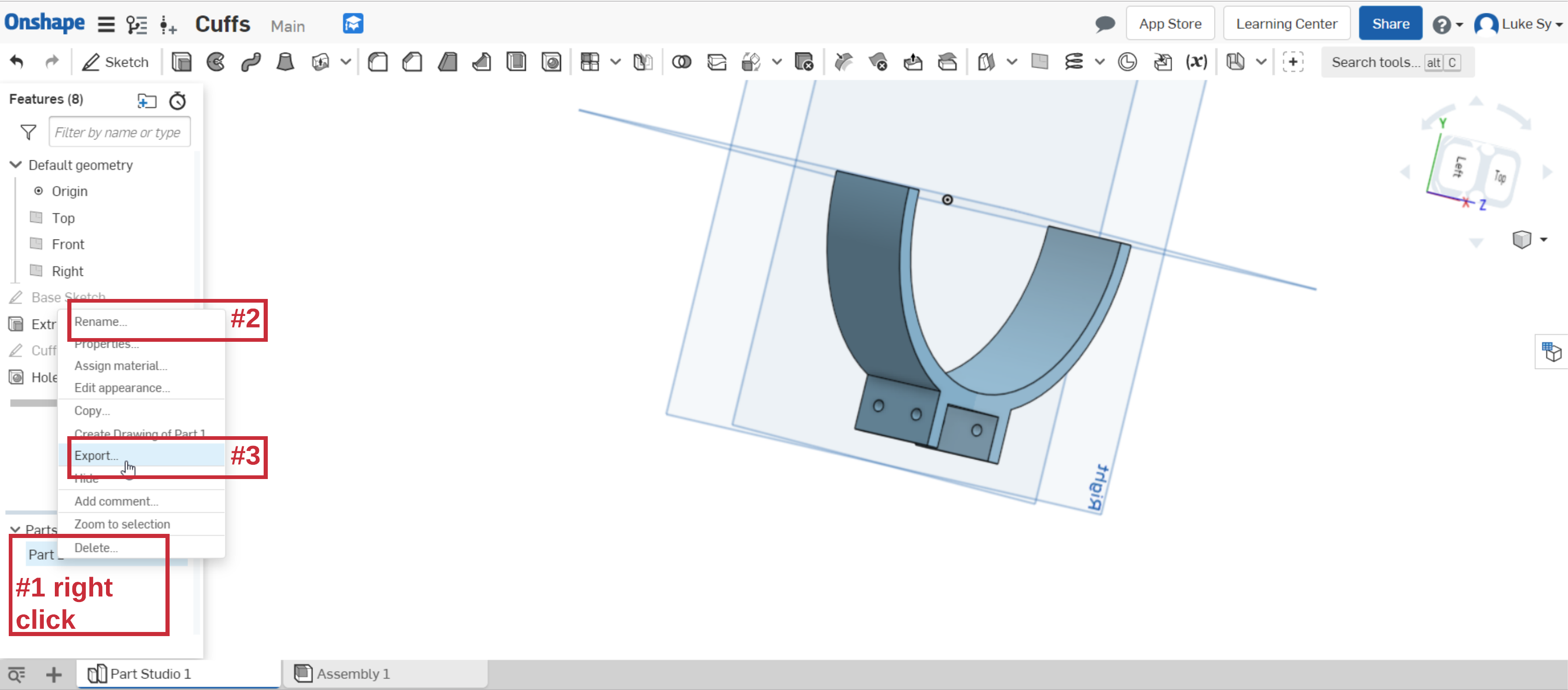
Export the part in the desired format (e.g., STL) for 3D printing (#1 and #3). To rename the part, click (#2).
3D Printing
If you are a UNSW student, you may want to explore the Maker space (link) and use their 3D printers. At the time of writing, they charge AU$3 per hour.
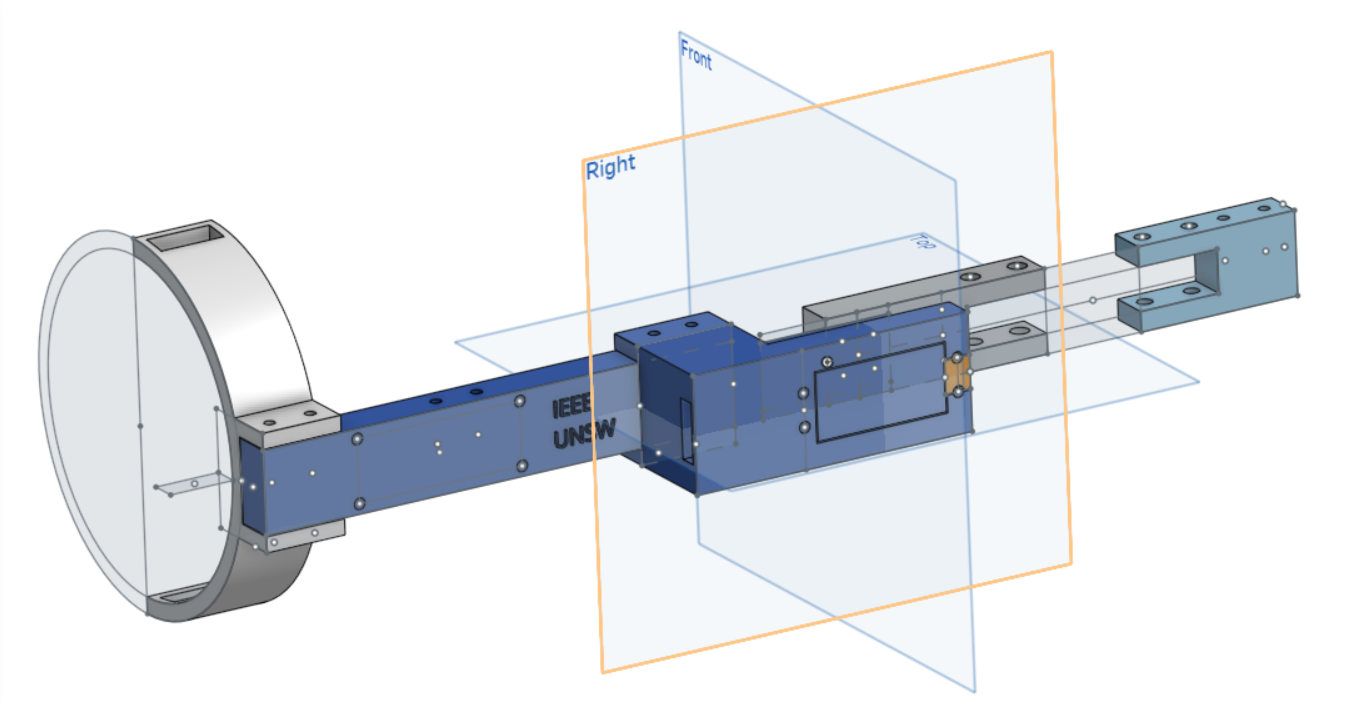
Full Exo Arm Model
After designing the cuffs (Sec. [sec:s01-cuff-making]), you should now have the basics of designing your own parts for 3D printing. We challenge you to design your own exoskeleton arm model! The exoskeleton arm will most likely consist of the following parts: i) biceps, ii) motor holder, iii) fore arm (two subparts), and iv) cuffs (now done). A sample exoskeleton arm CAD model is shown below (Fig. [fig:s01-exoarm-CAD-snapshot]). The onShape project can also be viewed here.
S02 - uC Programming and Control
In this section, we will be teaching the basics of microcontroller (uC) programming and the intricacies related in controlling an exoskeleton device. Specifically in this tutorial, we will show you how to interact with each of the sensors and actuators embedded in the exoskeleton arm, and then finally combine all of them together to control the arm using a PID controller. This project will be using a STM32F103 board, specifically the board more commonly known as blue pill.
Work environment setup
Installing the Arduino IDE.
The easiest way to start programming the microcontroller is through the Arduino IDE. First open the following website link. Then scroll down and download the appropriate installer for your operating system. Run the executable file you have just downloaded and you should be greeted with the following screen (may vary depending on your operating system).
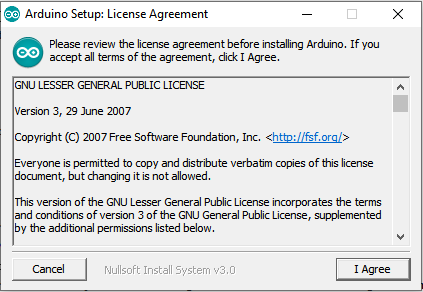
Click ’I Agree’. In the next screen ensure that ’Install USB driver’ and ’Associate .ino files’ are marked and click ’Next’.
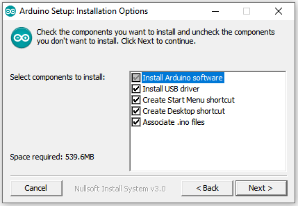
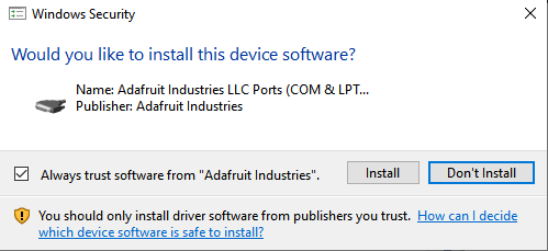
Then select the destination folder and hit ’Install’. Once completed you can close the current window. Some prompts to install some USB drivers should pop up. Select ’Install’ on all prompts that appear.
Configuring the IDE
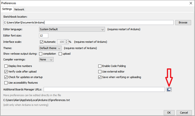
Open the Arduino application and navigate to File → Preferences. Click on the button on the right of ’Additional Boards Manager URLs’ (indicated in Fig. below). Copy the following address into the textbox that appears and hit OK.
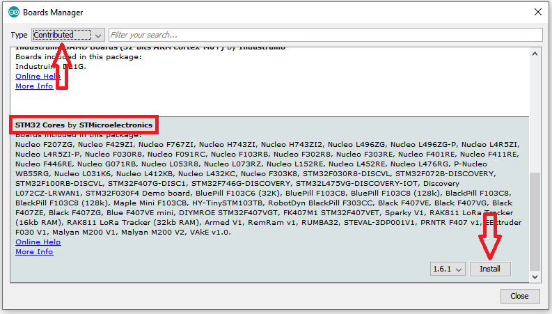
Hit ’OK’ again to exit the preferences menu and navigate to Tools → Board → Board Manager. Under ’Type’ select ’Contributed’. Scroll down and install the latest version of ’STM32 Cores by STMicroelectronics’. This should take a while. Upon successful installation you may close the window.
We’re almost there. As the microcontroller board (bluepill) used was for hobby-ist (i.e., free), we had to install another hardware library.
Download
Arduino_STM32-master.zipfrom link. Additionally, here’s the link to the github repo.Extract to
C:\Users\<username>\Documents\Arduino\hardware. Create thehardwarefolder if it doesn’t exist. The directory listing should look like below.hardware \- Arduino_STM32-master \- LICENSE \- README.md \- STM32F1 \- STM32F4 \- drivers \- toolsRestart the Arduino IDE.
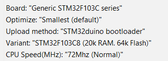
Set the IDE board settings (under Tools tab) to the following. If Generic STM32F103C is not on the list, make sure you double check the prior step.
Ensure to select the correct COM port (Tools → Port)
For Windows 10, run
C:\Users\<username>\Documents\Arduino\hardware\Arduino_STM32-master\drivers\win\install_drivers.batto install the serial driver. Click “yes” if admin permission is requested. See link for more details.
[Optional] Blink
Nothing to fancy here but just a sanity check to make sure our microcontroller (uC) is working. Feel free to skip. See github code.
The aim of this task is to repeatedly blink the on-board LED (on for one second and off for one second). This feedback will allow you to determine if you have successfully set up the software and are able to communicate with the microprocessor.
Initialise the LED pin (e.g., PC13) to act as an output. The function
void setup()runs instructions at startup everytime the board is powered on or reset.void setup() { pinMode(PC13, OUTPUT); }Write your code on the function
void loop()to indefinitely flash the LED. If it’s your first time writing an Arduino code, see next item for detailed description.void loop() { digitalWrite(PC13, HIGH); // turn the LED on delay(1000); // wait for a second digitalWrite(PC13, LOW); // turn the LED off delay(1000); // wait for a second }digitalWrite()takes two arguments, the pin and the state. In the code above, we set pin PC13 to ’HIGH’ or ’LOW’. Setting the output ’HIGH’ will send a high voltage level (3.3V) to the pin and turn on the LED. Setting the output ’LOW’ will turn off the LED.delay()will cause the micro-controller to wait 1 second before executing the next command. For a 1 second delay, the value will be 1000.Compile and upload the code to STM32.
Making the arm move (Motor test)
The aim of this task is to make the exoskeleton arm (motor at the elbow joint) move. See github code. The primary actuator we will be using is a servos motor. Servo motors have integrated gears and a shaft that can be precisely controlled. In this project, the servo motor MG996R (torque 9.4 kg/cm at 4.8V) can be controlled by the duty cycle of a pulse width signal ( datasheet).
Install the Servo library by Michael Margolis through the Library Manager (Sketch → Include Library → Manage Libraries). This library will be used to send pulse width signals of different width to the servo motor.
Add the code below for initialisation, and initialise
Servo myservowhich is the (software) object that we will use to control the motor.#include <Servo.h> #define MOTOR_PIN PB1 #define MOTOR_MAXPOS 125 #define MOTOR_MINPOS 0 #define DELAY 2000 Servo myservo;Again, add the code below to
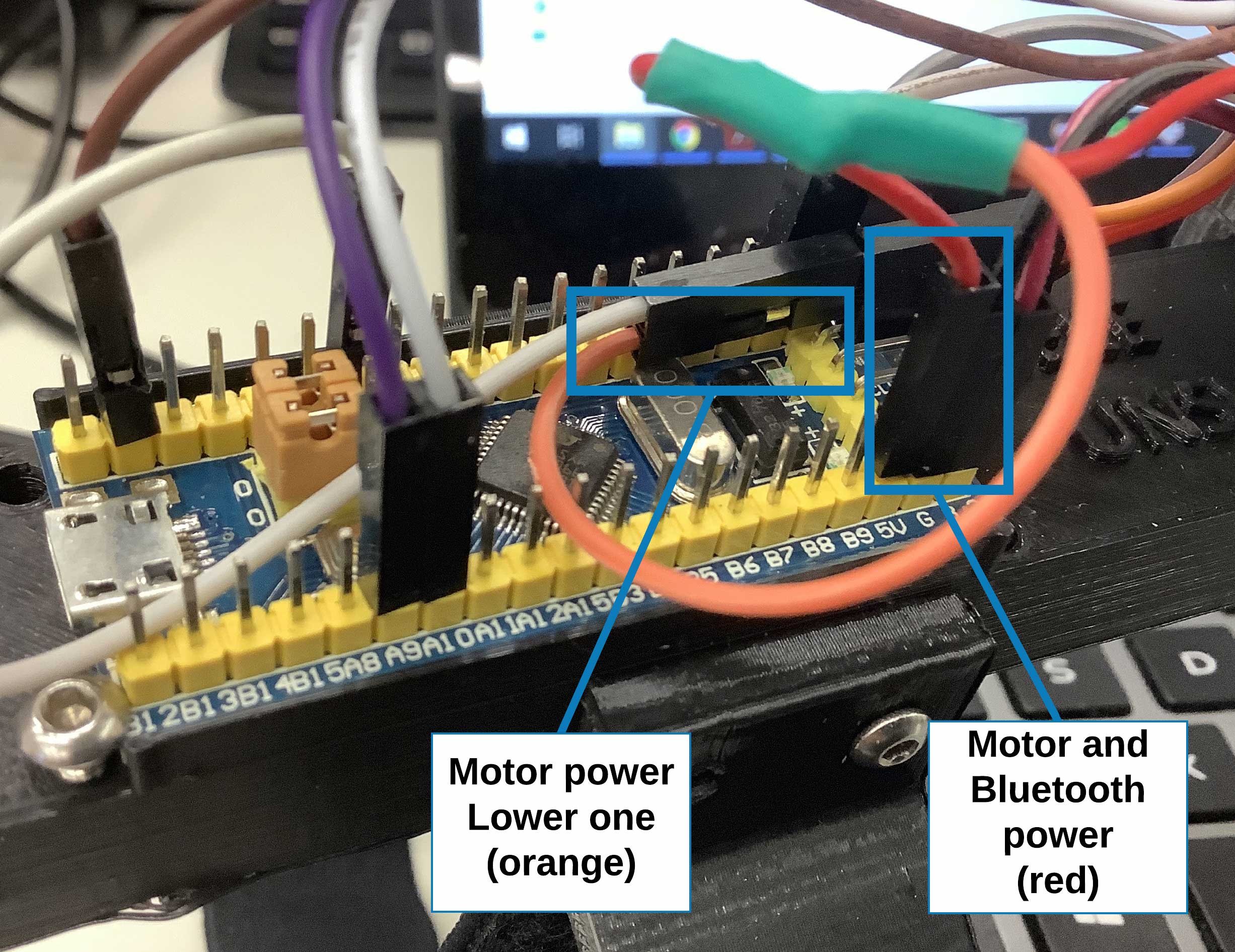
setup()to configuremyservowith the corresponding STM32 pin. Lastly, let us command the motor to go 0∘.void setup() { pinMode(MOTOR_PIN, OUTPUT); myservo.attach(MOTOR_PIN); myservo.write(0); delay(DELAY); }Compile and upload the code to STM32. After uploading, unplug the exoarm, reconnect the motor power, and then power the exoarm
Try moving the arm. You should feel that the motor is actually strong enough to resist normal movements.
Challenge
Modify the existing code to make it move through a range of motion, let’s say from 0 to 90 degrees. Don’t make the motor move past 120 degrees or you might damage the 3D printed body. We highly recommend you add a range check (see code snippet below) when commanding the servo motor. For the solution, see github motor rotate code.
  if(pos < MOTOR_MINPOS) pos = MOTOR_MINPOS;
  else if(pos > MOTOR_MAXPOS) pos = MOTOR_MAXPOS;
  myservo.write(pos);
Force sensing
This section aims to introduce you on sensing modalities to understand the user’s intention with regards to controlling an exoskeleton. In this tutorial, we will specifically sense from a load cell, a kind of 1D force sensor. For more details, see github code, datasheet, and similar projects. To be specific, the load cell’s resistance changes depending on where force is applied. This sensor is similar to what weighing scales use. The change in resistance is typically small and additional circuitry is needed. In our case, a wheat stone bridge of resistors coupled with an amplifier is needed to translate the signal into something our microcontroller can understand.
Install the HX711 library by Bogdan Necula, Andreas Motl (at the time or writing, v0.7.2) through the Library Manager (Sketch → Include Library → Manage Libraries). This library will be used to read the (uncalibrated) weight from the load cell.
Initialise
HX711 scalewith the code below which is the (software) object for communicating with the load cell. For debugging purposes, we also initializedSerial.#include "HX711.h" #define calibration_factor -7050.0 #define LOADCELL_DOUT_PIN PC14 #define LOADCELL_SCK_PIN PC13 HX711 scale; void setup() { Serial.begin(9600); scale.begin(LOADCELL_DOUT_PIN, LOADCELL_SCK_PIN); scale.set_scale(calibration_factor); scale.tare(); // reset the scale to 0 }The force is then read through
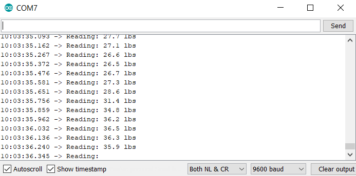
scale.get_units(). The value sensed by the scale can be in pounds(lbs) or kilograms depending on the calibration factor.void loop() { Serial.print(scale.get_units(), 1); Serial.println(" lbs or kg(?)"); delay(10); }Compile and upload the code to STM32. To test, run your favorite serial monitor (e.g., Teraterm or the Arduino IDE builtin serial monitor, Tools → Serial Monitor). See Fig. [fig:s02-loadcell-sample] for sample output.
Feedback control - PID
Now, it’s time to bring it all together! Without a sensing and control loop, the exoarm will be stuck at a certain elbow angle incapable of knowing the user’s intention. In this tutorial, we will sense from the load cell and command the servo motor to move accordingly using a proportional–integral–derivative (PID) controller. For more details on what a PID controller is, we encourage you to watch/read explanation at youtube and (full systems and control book). See github code.
Note: Only the code related to the PID will defined in the tutorial below. The code for the motor and load cell was left for reader to figure one. Refer to the prior sections if needed.
Initialise the parameters and corresponding variables for the PID controller.
#define K_P 0.3
#define K_I 0.0
#define K_D 0.0
double error, new_error, int_error, diff_error;
void setup() {
  // ...
  error = 0.0;
  int_error = 0.0;
  diff_error = 0.0;
  // ...
}
The code below shows how each proportional, integral, derivative components are calculated. The sum of the error (deviation of actual) is fed back to
posand the servo motor.void loop() { new_error = scale.get_units(); int_error += error; diff_error = new_error - error; error = new_error; // proportional + integral + derivative pos += K_P*error + K_I*int_error + K_D*diff_error; if(pos < MOTOR_MINPOS) pos = MOTOR_MINPOS; else if(pos > MOTOR_MAXPOS) pos = MOTOR_MAXPOS; myservo.write(pos); }Compile and upload the code to STM32. After uploading, unplug the exoarm, reconnect the motor power, and then power the exoarm
Try moving the arm. You may feel that the exoarm is not reacting as fast as you hope it to be. It may even oscilate as certain times. This behavior is normal! Try tweaking the parameters for a faster reaction time and more stable control.
Challenge: Exoarm Teleoperation
We haven’t talked about it much in this section but the exoarm also has a bluetooth attached. We challenge you to make two exoarms to talk with each other having the slave device imitate what the master device is doing. For more details, see github codes master pid, slave pid, or similar projects. See youtube video for sample demo.
You will need to setup the HC05 bluetooth module to connect with each other. You may want to use github code btpassthrough to configure the bluetooth module.
Enter bluetooth AT mode (configuration mode) by unplugging the exoarm, press and hold the bluetooth key button, and then plug the exoarm again. The bluetooth led should blink at 2 sec. interval when in AT mode.
Enter the following configuration for the slave device. Note that you will have to enter them one by one via serial and the bluetooth device should respond with ’OK’ for each step. When changing roles, the bluetooth device might automatically reboot.
AT+RMAAD (To clear any paired devices)
AT+ROLE=0 (To set it as slave)
AT+ADDR (To get the address of this HC-05, remember to jot the address down as it will be used during master configuration)
AT+UART=38400,0,0 (To fix the baud rate at 38400)
Code your own or upload this code to the slave exoarm. Note that by default, the bluetooth module buffers and processes messages by batch (every 1 sec). To reduce this interval, use
Serial1.setTimeout(50);at setup.Enter the following configuration for the master device.
AT+RMAAD (To clear any paired devices)
AT+ROLE=1 (To set it as master)
AT+CMODE=0 (To connect the module to the specified Bluetooth address and this Bluetooth address can be specified by the binding command)
AT+BIND=xxxx,xx,xxxxxx (Note the commas instead of colons given by the slave module.
AT+UART=38400,0,0 (To fix the baud rate at 38400)
Code your own or upload this code to the master exoarm.
Here’s a debugging tool if things are not working as planned. github master rotate will use the master device to send messages to the slave device to rotate the arm from 0 to 125∘ and backwards.
S03 - Computer interaction
In this section, we will be teaching the basics of interfacing an exoarm and a computer using a bluetooth module. Specifically, we will model the orientation of the exoarm, and make a game out of our input interface. Note that these games can be used to gamify rehabilitation.
Install processing IDE
Download processing IDE from link. If using a Windows 10 64 bit machine, the downloaded file will be something like
processing-3.5.3-windows64.zip. See link for details.Extract the zip file and run
processing.exe.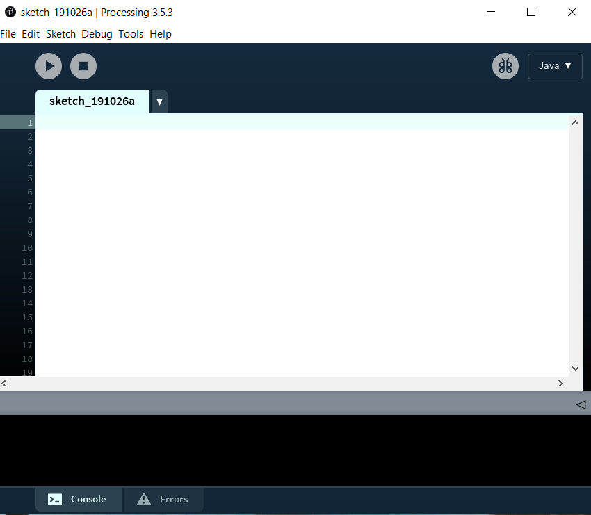
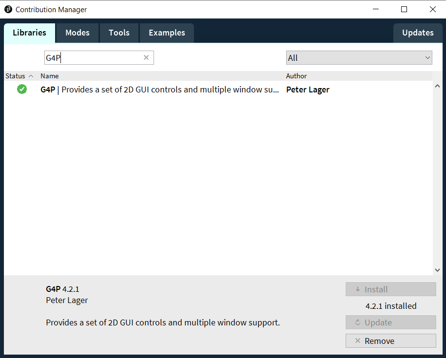
Install G4P library via Sketch → Import Library → Add Library.
Orientation Estimation
This section downloads an orientation estimation algorithm, also known as Attitude and Heading Reference Systems (AHRS), into the STM32. The exoarm will output the orientation state as serial data both via USB and bluetooth.
Load basicAHRSandFB code to STM32. Make sure
SerialDebugis set totrueand that the motor power is disconnected. Note that the code was based on Kris Winer’s MPU9250 code.Power STM32 through your laptop and connect with your favorite serial monitor. You should see something like the figure below.
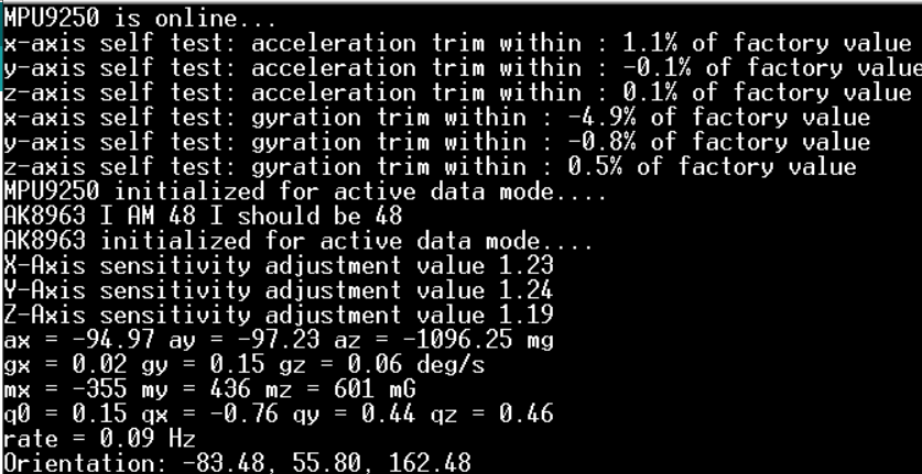
Specifically, the exoarm sends serial data
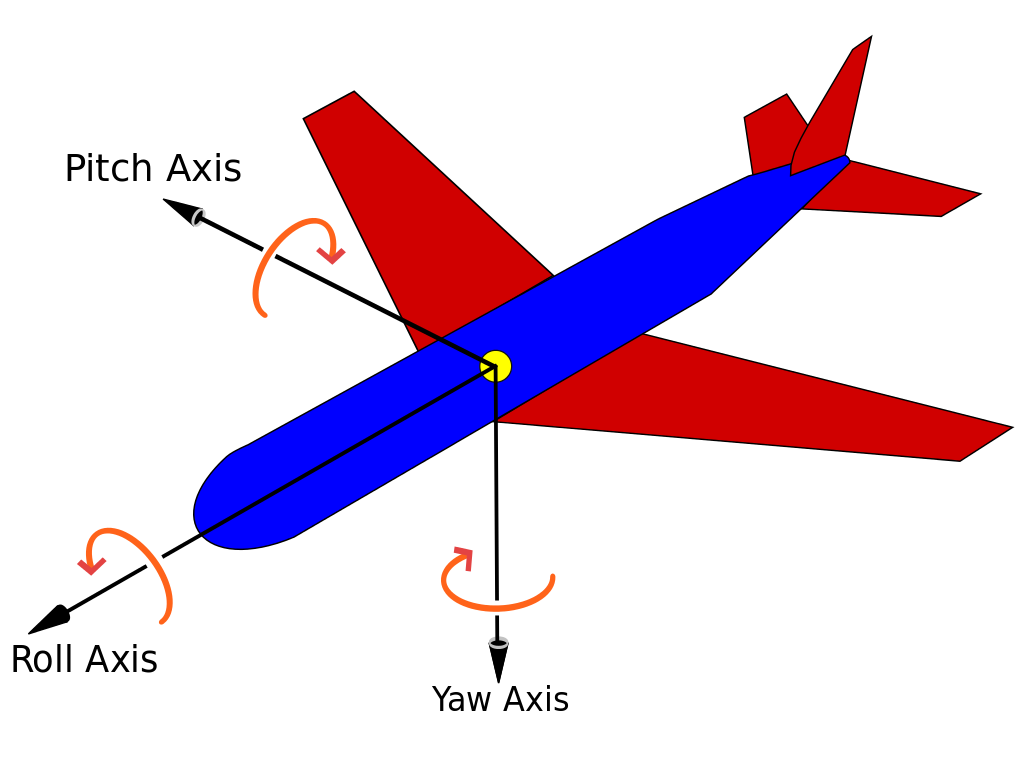
Orientation: yaw, pitch, roll, elbow angle. Try moving around the device and observe how orientation changes with your movement.Note that the code used Tait-Bryan angles to define the orientation of the bicep. Specifically, z-y′-x″ (intrinsic rotations) also known as yaw, pitch and roll.
Now disconnect the device, connect the motor power and power the device through an external power source.
Connect your PC to the bluetooth module
EXOARM<ID>. The default password is1234. ID is written on the exoarm label.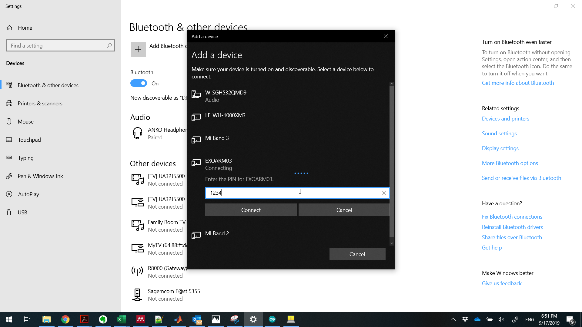
Set the COM port to the corresponding bluetooth port and read incoming data via your favorite serial monitor.
By default, the code runs
MadgwickQuaternionUpdate. GiveMahonyQuaternionUpdatea try as well (comment out the filter you’re not using) and see if you can distinguish any difference.
Bicep 3D viewer
This section aims to receive the orientation serial data from the exoarm and model the bicep using the processing IDE.
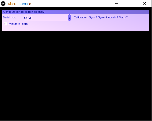
Load the cuberotatebase code in processing and run. You will see a blank box as shown below.
Select the corresponding serial port (whether cabled or via bluetooth), and check the
Print serial datacheckbox. If the serial communication is via bluetooth, the bluetooth LED on the exoarm will blink slowly (every 2 sec) if connected. You should be able to read serial data describing the exoarm bicep orientation.Let us now draw a rectangle to model the exoarm biceps by adding the code below (see comment on where to add the code). If you re-run processing, it should look like the figure below.
// Add translation and drawing code here
translate(boxLength/2, 0, 0);
fill(0, 0, 255, 128); //blue
box(boxLength,2*boxWidth,boxWidth);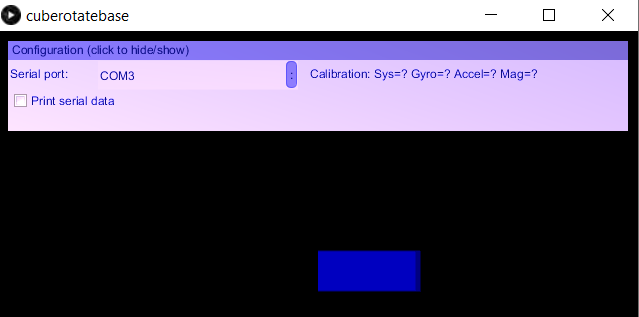
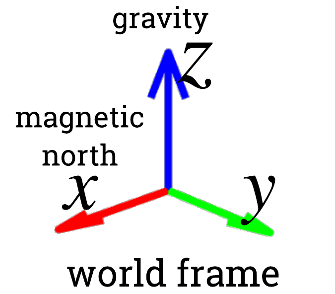
Now using the functions below, we will want to rotate the coordinate system of our 3D model such that it is aligned with the actual exoarm in the world frame. Do so by systematically trying different values (
yaw,pitch,roll) as input to therotatefunctions. The left handed coordinate system of the model (processing) is shown in the figure below.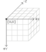
// Add rotation code here
rotateY(radians(?));
rotateZ(radians(?));
rotateX(radians(?)); // extrinsic rotation
In theory, the (actual) world frame is a right handed coordinate system as shown in the figure below. The conversion between left to right coordinate system involved multiplying a basis vector by −1, plus some fixed offset rotation between the sensor to exoarm frame. In this workshop, we suggested to do the trial and error approach for simplicity :p
If you have the correct
rotateordering, the orientation of the exoarm should move similarly to the exoarm model (e.g., if you rotate the bicep to the left, the box will also rotate to the left).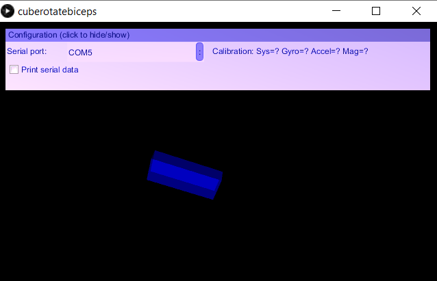
Sample solution can be found at cuberotatebiceps github.
Arm 3D viewer
This section aims to extend the bicep 3D viewer by adding in the arm.
We will be extending our code from the prior section (Bicep 3D viewer). As the feature we want to achieve starts to be become more complex, let us first define some of the drawing functions below. See link for processing’s 3D tutorial.
translate(x,y,z)translates our model point with offset (x, y, z).rotateX,rotateY,rotateZrotate the coordinate system along the X, Y, or Z axis.box(x,y,z)draws a box centered at the point where the model is currently at.pushMatrix()pushes the current transformation matrix onto the matrix stack. As we’ll only have one object, unlikely to use it in this project.
Using a combination of
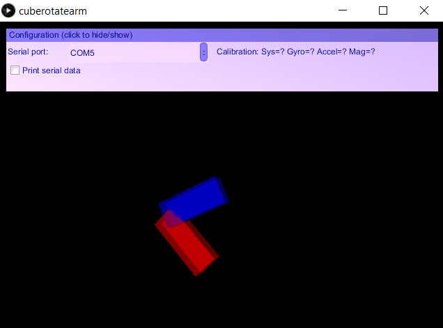
translate(x,y,z), the correctrotatefunction, andbox(x,y,z), draw the arm at the tip of the bicep. From better visualization, let’s color the arm red using the codefill(255, 0, 0, 128);. You may also choose to inspect the model that it is correct before connecting with the exoarm via serial. The resulting model should look like the figure below.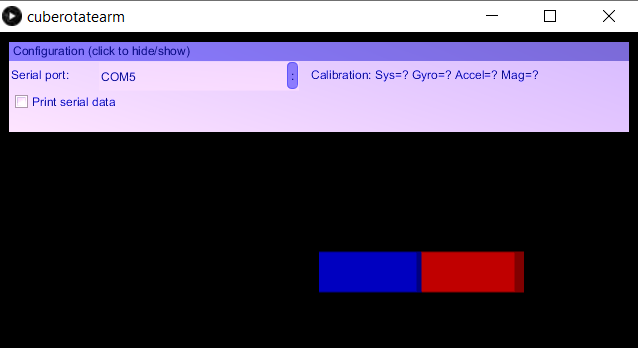
Try different exoarm orientation specially the elbow bending and see if the model is representing it correctly.
Sample solution can be found at cuberotatearm github.
Challenge: Game interaction - Simple pong
In this section, we will be using the exoarm as a device controller for playing a simple pong game.
Load the simplepongbase code in processing and run. You will see an interface as shown below. Note that the bar on the right is controlled by the mouse y position.
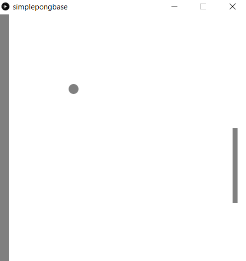
Modify the code (take code snippets from Arm 3D viewer) such that the bar y position is controlled by the elbow angle. The modification will involve the following parts.
UI control for selecting the serial port. Involves code at
void setup(), and handlers such asvoid handleDropListEvents(...)andvoid handleToggleControlEvents(...).void setSerialPort(String portName)void serialEvent(Serial p)Change
mouseYinto a normalised elbow position.mouseYranges from 0 → 480 while elbow angle ranges from 0 → 125.
Sample solution can be found at simplepong github.
Challenge: Control Exoarm via GUI v1
Modify the Arm 3D viewer GUI such that a slider panel controls the the elbow angle of the exoarm. Note that for the first version, the model does not display a similar orientation as the exoarm.
Make a copy of your Arm 3D viewer code. We will be working on the this copy as our base.
Add a GSlider into the panel
GSlider   sliderPanel;

void setup() {
  ...
  sliderPanel = new GSlider(this, 5, 100, 640, 20, 20);
  ... }
For simplicity, let us delete the contents of
void serialEvent(Serial p).Define the GSlider handler
public void handleSliderEvents(GValueControl slider, GEvent event) {
  ...
  elbow = slider.getValueF() ...
  ...
}
Upload this code to the slave exoarm.
Select the corresponding serial port in the GUI to connect with the exoarm. Changing the slider panel should remotely change the elbow angle of the exoarm.
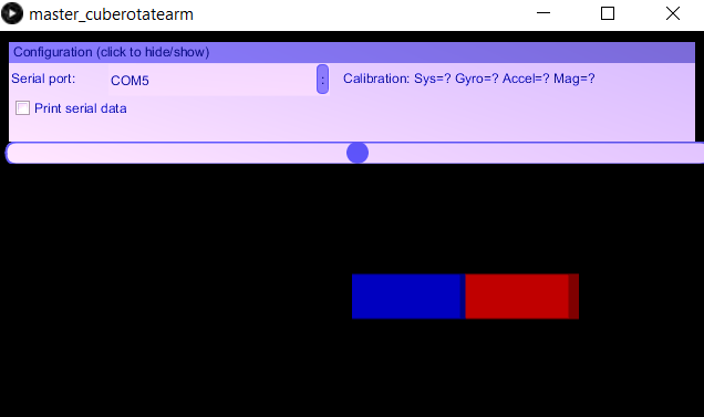
Sample solution can be found at master_cuberotatearm github.
Challenge: Control Exoarm via GUI v2
Modify the Arm 3D viewer GUI such that a slider panel controls the the elbow angle of the exoarm. Note that in this second version, we want the model to display a similar orientation as the exoarm.
Make a copy of your Control Exoarm via GUI v1 code. We will be working on the this copy as our base.
Insert back the deleted
void serialEvent(Serial p)(refer to Arm 3D viewer).Modify the basicAHRSandFB code such that the exoarm sends bicep orientation state but receives elbow state. Refer to slave pid code.
Check if the serial read and write events are interfering with one another. If they do, fix accordingly.
To test, select the corresponding serial port in the GUI to connect with the exoarm. Changing the slider panel should remotely change the elbow angle of the exoarm.
I still don’t have a sample solution so if you successfully done this part. Please send me the solution
l.sy@unsw.edu.au.
Electromyography (EMG) control
FUTURE WORK
Reading signal
Feedback control
Acknowledgements
The author would like to thank UNSW Arc (funding and venue) and the IEEE NSW section for supporting our student branch in this endeavour.
And the following people who helped with this workshop and documentation:
Han Wen, Philip Byrnes-Preston, and Ben Xia for the idea and random questions associated in making this workshop
Alan Ngo for Sec. [sec:control-ide-setup].
Logan Peters for initial versions of Sec. [sec:s02-blink], [sec:s02-motortest], [sec:s02-force-sensing].
Martin Lunel Agbayani for Sec. [sec:why-stm32].